![]()
|
Clint Busenitz |
8:00 AM to 5:00 PM (Monday thru Thursday). 8:00 AM to 12 noon (Friday) www.vettermanxhaust.com
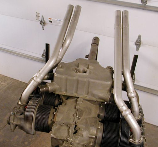
Super Cub dual muffler exhaust
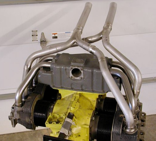
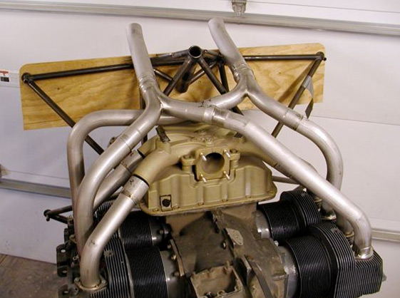
Vetterman Exhaust is pleased to announce the availability of our light weight experimental Super Cub dual muffler exhaust. It weighs 12.5 lbs fully installed with nuts, bolts, gaskets, shrouds, ect. The primary pipes are 1.5" in diameter, and increase to 1.75" for the tail pipes. 1 muffler has a cabin heat shroud, and the other muffler has a carburetor heat shroud. The crossover pipes that cross in from of the oil sump are indexed to add an optional 3rd heat muff for extreme cold weather operations. For more information on price and lead times, give us a call.
3/31/2014
There have been many requests for a muffler system on RV's that use the horizontal induction engines. Some of the requests were for noise reduction and some were for more cabin heat. When I was working full time I really didn't have the time to design a new system, dyno and flight test it. So when I decided to retire and turn things over to Clint, my first order of business was to capitilize on all the knowledge and experience gained and come up with a new concept exhaust system. My goal was a system that would produce as much or more power as the standard crossover system and fit on a number of engine/airframe combintaion. I discussed the concept with Clint and he being the energetic and talented young fellow that he is, went to work on it. When I looked at the prototype that Clint designed on the M1B, I knew it just might work. We also installed the system on the standard vertical sump and superior sump fixtures and it fit them also. We sent the system down to G3I in Denver and Thomas dyno tested it. The test numbers came out well, so we knew the pipe lengths were right where they needed to be. Next step was to test fly it on my RV-7A. I now have the tests complete and am very satisfied with the test results listed below
Tests were done at 8000 ft. Density Altitude
2450 rpm 22.2 in. mp TAS 193.5 mph EGT #1 1312 #2 1336 #3 1322 #4 1316
2500 rpm 22.0 in mp TAS 196 mph EGT #1 1312 #2 1325 #3 1327 #4 1309
2550 rpm 22.0 in. mp TAS 198 mph EGT #1 1328 #2 1329 #3 1327 #4 1320
The data listed above concurs with other tests conducted using the same aircraft, ie. my RV-7A. Note the close egt spread at 2550rpm, which is where this system likes to be run. This should be a good setup for all the fixed pitch props running out there.
The trombone system will fit on the following aircraft: RV-6-6A RV7-7A and RV-8, we are not sure of the 8A at this time. The system will fit on these engines 0-320/0-360 vertical updraft, IO-360/375 Superior cold air sump, and Lyc. IO-360 M1B.
We are offering this system with mufflers only, no tail pipes and can only be ordered directly from us at a price of $1395 plus shipping
Vetterman Exhaust, Inc. has been in business since 1990 and offer exhaust systems for all RV models and engine combinations, from the RV-3 thru the RV-10. We currently manufacture 31 different systems for the RV line.
All systems are manufactured from 321 (industry standard) stainless steel tubing. We do all the bending in-house, which assures that all systems will fit the engine/air frame. We install slip joints in critical locations which help keep system breakage to a minimum Flanges are precision laser cut from � - 304 stainless. Each flange is faced perfectly flat so there is excellent sealing between it, the blow proof gasket and the cylinder.
All welding is done using the TIG process with appropriate filler rod and an argon purge on the inside. The argon purge keeps stress levels and potential breaks to a minimum.
Why is Vetterman Exhaust the best in the industry?
- RV exhausts are built for RV's by an RV builder. We manufacture a quality product that will fit on the engine/aircraft. It is not necessary to modify the cowl or airframe to install any model of exhaust that we manufacture.
- We provide enough area for cabin heat capabilities.
- We design the system to be flexible so breakage is not a concern on long trips away from home.
- We tune our exhaust systems. Our tests show that most popular styles produce the same amount of TAS at 75% or lower power settings while burning about the same amount of fuel.
- We stand behind our product. If there is a problem during the 1st 100 hours of operation we usually repair it at no cost.
- Yes, we sell direct to the builder. We encourage you to give us a call and discuss which system will be the best for your aircraft/engine combination.
- We manufacture exhaust systems for all models of Lycoming, ECI, and Superior engines that builders are installing on their RVs.
The standard crossover exhaust...
...which has been a standard since the RV-6 was introduced is available only by ordering directly from us. It is available in the standard 1 3/4 primary pipes and 2 inch tail pipes, or you can order it with dual mufflers. This system fits the following combinations of engines and airframes. RV-6-6A, RV-7-7A, RV-8-8A, RV-9-9A, using the 0-320 D or E model and the 0-360 A1A or similar model. It will not fit the 0-320 conical engines or the H2AD models. These systems are also available but are a special order.
The new 1 1/2 inch system is also available only by direct order from us and it is our latest design. When we designed the exhaust system for the LSA aircraft, we tested this system on the 7A, not knowing how it would perform on the 0-360 engine. During the testing, most of the engine temps. etc were very close to data already listed here on this site, except the TAS was typically 197 mph whereas the standard system yielded 196 mph. We decided to have both system dyno tested and were quite surprised at the results. The dyno tests are available for your viewing on www.g3ignition.com . This graph shows very interesting results, so take a look at and decide which system is the best for your aircraft. The 1 1/2 inch system weighs @ 2 lbs less than the standard 1 3/4 inch system. It is also available with mufflers just like the standard 1 3.4 inch system, however I am not done testing this system for comparable power with straight pipes vs. mufflers. So far, it appears there is very little difference. We will continue the testing and post the results here later on. Give us a call and check out our prices or to get any more information.Exhaust testimonial.
We got a call from Mike Seager wanting to purchase a new O-320 muffler system as the one on the RV-7 has 4000 hours on it. Mike explained there were some thin areas on the tail pipes and with that many hours, it would be best to just replace it with a new one. As far as I know this system is the highest time one out there. Mike also told us that it had been trouble free and is sure the new one will be just as dependable.Tail Pipe Mount
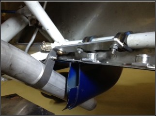
Here is a picture of the very simple tail pipe mount that I have been testing for @100 hours now. It is simply a 5 inch piece of 1/8 X 3/4 inch aluminum strap, with 2 ea. WDG 12 clamps mounted on the bottom engine mount tube. It can be used in conjunction with the standard mount kit sent out with the exhaust. Use the vertical method as shown in the mount kit and then use this for the horizontal support. I wanted to see how and when this set up would break and so far it has worked very well. It is also very important to keep the ball joints free by lubing them with mouse mild or some other high temp anti seize.
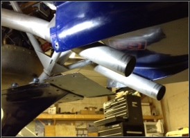
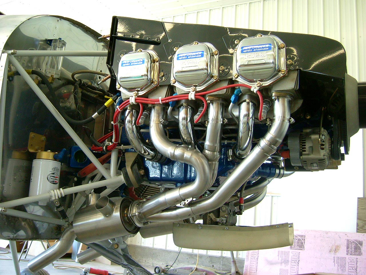
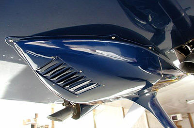
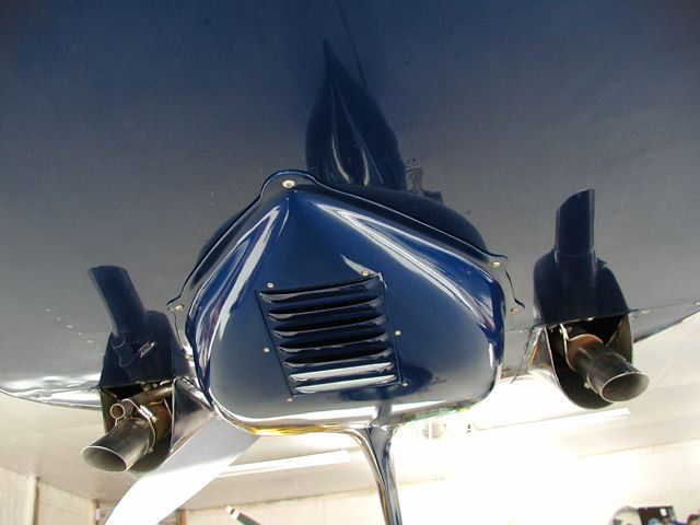
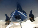
Standard system mounted on my 7A
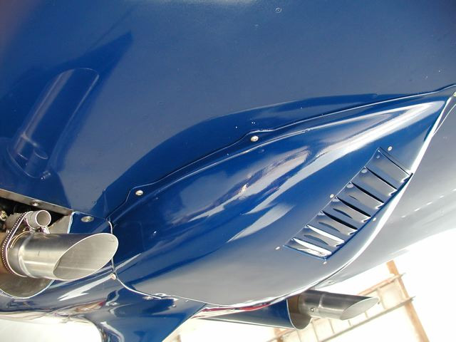
...showing the sub cowl mod that has been on the aircraft for several years. I get many request for pictures of it so here it is.
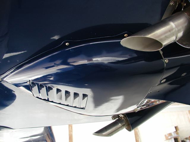
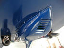
Another picture of the sub cowl from a different angle and it also shows the angle of the tail pipes.
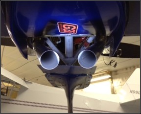
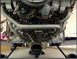
Rear view of the subcowl and also the tail pipes. Notice the angle in toward each other, as that is the way they are designed to give maximum heat muff clearance in the cowl and be at the proper angle to alleviate exhaust pulsing on belly skin.
Here is picture of the standard carb heat muff from www.robbinswings.com . This carb heat muff will work well and is available directly from us or from Robbins Wings.
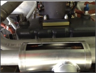
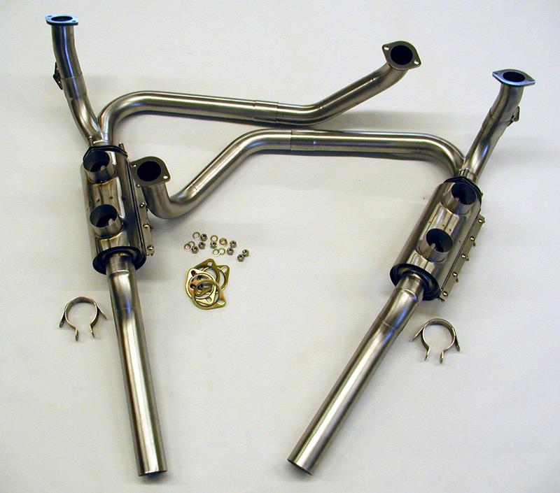
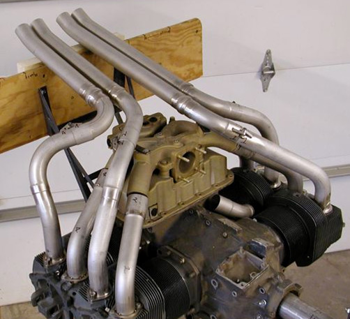
This picture is the 1.5 inch system with dual mufflers installed.
Muffler Systems Exhaust Testing Frequently asked questions. The 3 into 1 collector muffler system is standard on the RV-10 I-O-540 engine. The standard 0-360/320 crossover system can be ordered with mufflers instead of the 2 inch tail pipes. Mufflers are not available for horizontal induction injected engines. This new system was designed in 2006 with a take apart style ball joint. If noise regulations get stricter, the tail pipes can be removed and a set of mufflers installed. Test show a 6 DB noise reduction with mufflers. Another advantage of the muffler is the increase in cabin heat available. The RV's up north enjoy a warm cabin even in the coldest winter months.
Almost every system or style of system has been tested before it is produced. No, we don't have or use a dyno for testing. We install the system on the actual aircraft, flight test it, fine tune it, then produce it. We are often asked to build a system that will produce more HP than anything available and the answer is: If it were possible and we could get it inside of the cowl, it would be on my RV. There is no such thing as a free lunch when it comes to RV exhaust systems. Got A Question About Heat Muffs?
Contact Rick Robbins at www.RobbinsWings.com.What is the correct EGT probe location?
EGT probes should be mounted one and a half to two inches below the cylinder port. This places the probes in the flame front which will give the most correct reading.What is the correct torque on the exhaust flange bolts?
We recommend 140 to 180 inch pounds. Anytime the exhaust is removed the internal star washers need to be replaced. The blow proof gaskets can be used again when reinstalling the system.How do I keep slip joints and ball joints lubricated?
We highly recommend that every time the cowling is removed the exhaust should be inspected and Mouse Milk penetrate be applied to all slip joints and ball joints.Can I wrap my exhaust with automotive type of wrap material and obtain more power?
Any material on the exhaust will shorten it's life and failure will occur. We are using air cooled engines and one the best heat sinks on the engine is the exhaust system. The mass air flow comes in and is forced down and around the cooling fins and then is directed over the exhaust system and then exited out the bottom. If the exhaust is covered it cannot aid in the cooling process. Our tests show that any type of wrap on the exhaust makes both the cylinder head and exhaust temperature run higher. The stainless steel used (type 321) will degrade if the surface temperature is over 1250 degrees F. We also did not find a power increase of any kind by wrapping the exhaust.How about ceramic coatings?
The jury is still out on them as to whether there is any benefit, however as stated above, they have the same effect as wrapping the exhaust. We do know that once a ceramic coating is applied, the system can never be repaired as it gets into the pores and welding is not possible. How about cooler cowl temperatures with either of the above? Yes, the temperature in the cowl will probably be cooler, but the engine produces so many BTU's of heat so it either is kept cool by the mass air flow or it stays in the cylinder heads.
Results of (3) Exhaust System Tests
...by RV exhaust guru Larry Vetterman
RESULTS OF EXHAUST SYSTEM TESTS (January '07)
I decided to conduct a comparative test of three different types of exhaust systems available for the RV's. The 4 into 1 collector system, the standard crossover system and the 4 pipe system. Each of these systems had previously been installed and flown a minimum of 50 hours on my RV-7A. Each one of these systems are considered standard exhausts for the RV's.The tests were conducted using the Flight Data System (APF 30) in the aircraft. It was my goal to measure True Airspeed, fuel burn, EGT's, gallons per hour, percent HP, and also monitor engine smoothness with each system. It was assumed that any instrument error would be the same for each system so it was not a concern. It was not a goal to measure the different sounds or noise levels that each system produced. The results on the RV-7A, I0-360 M1B engine, 265 hrs.total time, with ECI Titan cylinders are as follows. All flights were at 8000 ft. density altitude (taken from the Flight Data System) and full throttle
System 1: 4 into 1 collector This system required cutting a hole in the bottom cowl and bringing it out beside the nose gear. I then spent a number hours fabricating a fairing around the collector and tail pipe. I wanted a smooth fairing to get all the speed that I could.
Density Altitude 8000 ft. OAT 23.0 F. RPM 2400 MP 21.9in.
EGT's #1 1270 #2 1340 #3 1277 @4 1308
IAS 179MPH TAS 202MPH GPH 10.0GPH 71% power
Note This RPM produced a rough engine.
RPM 2500 MP 21.9
EGT's #1 1263 #2 1322 #3 1265 #4 1298
IAS 182MPH TAS 206MPH GPH 10.6 73% power
Note The engine was smooth at this RPM
RPM 2600 MP 21.9
EGT's #1 1265 #2 1325 #3 1271 #4 1294
IAS 186MPH TAS 210MPH GPH 10.9 76% power
Note The engine was very smooth at this RPM
System 2: Standard crossover for the M1B engine. No cowl modifications required.
Density Altitude 8000 ft. OAT 8.4 F RPM 2400 MP 21.3 in.
EGT's #1 1294 #2 1293 #3 1249 #4 1255
IAS 180 MPH TAS 202 MPH GPH 9.4 70% power
Note: The OAT was somewhat lower than in Test #1. Engine was smooth at the RPM.
RPM 2500 MP 21.3
EGT's #1 1305 #2 1291 #3 1250 #4 1250
IAS 182 MPH TAS 204 MPH GPH 10.2 72% power
Note The engine was smooth at this RPM
RPM 2600 MP 21.3
EGT's #1 1309 #2 1292 #3 1260 #4 1256
IAS 184 MPH TAS 208 MPH GPH 10.7 75% power
Note The engine was smooth at this RPM. The flight data system oscillated between 208 and 209 MPH so I used the lower number.
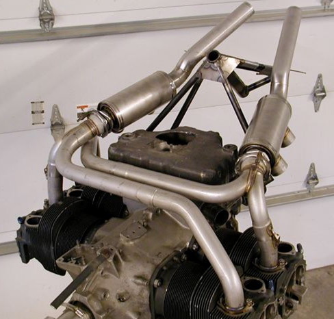
System 3: 4 pipe exhaust. No cowl modifications required.
Density Altitude 8000 ft. OAT 32.7F. RPM 2400 MP 22.4
EGT;s #1 1315 #2 1303 #3 1299 #4 1265
IAS 178 MPH TAS 202 MPH GPH 9.8 71% power
Note The engine was smooth at this RPM
2500 RPM MP 22.4
EGT's #1 1315 #2 1303 #3 1299 #4 1266
IAS 183 MPH TAS 206 MPH GPH 10.4 74% power
Note The engine was smooth at this RPM
2600 RPM MP 22.3
EGT's #1 1308 #2 1296 #3 1282 #4 1258
IAS 186 MPH TAS 210 MPH GPH 10.9 76% power
Note The engine was smooth at this RPM
The outcome of this test is somewhat in line of my thinking that most exhaust systems will perform about the same at power settings at or below 75%. Fuel burn may vary according to wx conditions and leaning techniques. My assumption is the variance in manifold pressures that were indicated are due to the different OAT's. Differences in EGT readings may be due to variations in probe locations on each system ie. The actual distance of the probes from the exhaust port.The factory literature for the 7A shows the top speed is 210 MPH and this test is in line with that speed. We all want to go faster, but in reality a couple more MPH's are hard to obtain and the answer may not be in the exhaust system alone but a combination of factors. I hope this test will help in selecting the right system for your aircraft- engine combination.
One test that I also conducted was to bring the throttle to idle during approach and landing to see if any of the systems would backfire and pop. I could not get any of the systems to do it as the fuel injection system (idle mixture) is set properly and there are no induction leaks on this engine.
Hartzell Blended Airfoil vs Whirlwind 200RV Series props on my RV-7A�.Larry Vetterman
I was very interested in comparing these two props and how each of them would perform on my RV-7A. This aircraft has become a test bed for almost all of the exhaust testing as well as other ideas that I or other builders suggest. Seems we all want to go just 1 mph faster and there has been a lot of discussion about prop performance. My 7A has the Hartzell Bended Airfoil with the 7496 blades so I knew a comparison test would be fun. I had a very good conversation with Greg Anderson of Whirlwind Aviation at OSH last summer and he was interested in doing the comparison. I also wanted to test the MT 3 blade but there was not one available at the time of the tests. After a couple of calls to Whirlwind, Greg informed me that a test prop was on the way. I must say that it was a beautiful piece of work and I was extremely careful with it as I had agreed that if I damaged it, I would pay for it.
Before I started the prop tests, I was very interested in the new electronic ignition that I had seen on the web. www.g3ignition.com . I called Tom and he agreed to install one on my 7A. I found the installation was simple for even me as electricity and I just don't get along. I tell people that I am so electrically challenged that I hire my neighbor to change my flashlight batteries. Oh well, I would bet that some electronics guru can't weld either. The hardest part of the installation was removing the Bendix mags. and installing the post that hooks up the G3. Now after flying it almost 100 hours, here are the reasons that I really like the G3. #1. Easy to install, even I could follow the wiring diagrams. 2. the system uses the existing mags and if there is an electrical failure, the mags operate normally. 3. the engine starts very well both hot and cold. 4. I can now run lean of peak if desired whereas before my M1B, with standard mags balked at anything beyond peak EGT. 5. I see a lower ghp with the G3 vs standard mags. 6. The M1B engine is extremely smooth with the G3. 7. I used the expensive Champion fine wire spark plugs(I had a set on the shelf) gapped to .021 however I understand that an inexpensive automotive plug can also be used.
Aircraft RV-7A, IO-360 M1B 180HP standard air intake and standard crossover system.
Test #1 Standard Mags vs. G3 ignition Hartzell Blended Airfoil prop. A series of flights were made in this configuration and the data was compiled and averaged. The flight data system was used for all of the following tests as in all prior tests. The G3 is a type of system that is easily forgotten and all it takes is to reach over and turn it off and see the difference in smoothness.
DA 7500ft. MP 22.7 RPM 2400 OAT 45.1 GPH 9.1 IAS 166mph TAS 189mph EGT #1 1387 #2 1358 #3 1370 #4 1340. G3 ignition OFF
DA 7500ft MP 22.7 RPM 2400 OAT 45.1 GPH 8.9 IAS 168mph TAS 191mph EGT #1 1400 #2 1372 #3 1377 #4 1345. G3 ignition ON Note: The G3 will allow a higher peak EGT which allows a fuel savings.
Tests were also conducted at 10,500DA and the important data shows 20.9 MP 2400RPM at 50 degrees rich of peak the IAS 158 TAS 186 9GPH while 50 degrees lean of peak yields IAS 154 TAS 182 8GPH. G3 ignition on.
In every test conducted with both props, there is a definite engine smoothness noted with the G3 on vs operating in the standard mag mode.
Discussion
The Hartzell blended airfoil data was obtained first as this prop was already mounted on the aircraft. On each flight the aircraft was full of fuel and I was the only occupant in the aircraft. I tried to fly a number of flights with the same or close temps so there would not be any advantage or disadvantage to either of the props. On days where the temperatures were quite different or the air was not smooth enough for the tests I quit testing and did not include any data. Most testing was conducted in the early morning hours as the air is stable and smooth. I did not want this test to be an all out burn up the engine etc. type of test as it is more important to gather data at legitimate cruise power settings and altitudes where we typically operate. The data gathered here is only one way to compare performance ie. using one aircraft for both props. Perhaps it is better that two aircraft that perform closely fly together and see how they each perform and then trade props and do the same test. I did not have that option available.
The Hartzell BA prop was previously dynamically balanced and has always been smooth. The owners manual sent along with the Whirlwind 200 states that the "engine/propeller must now be dynamically balanced before the first flight". I did not accomplish this for the series of test that I conducted, however I found the Whirlwind 200 to be extremely smooth at all RPM's and power settings.
I used an electronic scale to weigh both props. The Harzell as removed with the spinner installed and residual oil in the hub weighed 60 lbs. The Whirlwind 200RV prop weighed 38 lbs. and the spinner with attaching hardware weighed 3 lbs which is a total of 41 lbs. Taking 19 lbs. off the nose of the 7A made a difference in handling especially on take off and landing. It was possible to keep the nose wheel off the runway for quite awhile longer with the Whirlwind 200. I did not do a new weight and balance as there was nothing in the baggage compartment and the tests were with full tanks. I would note that if you are going to use the Whirlwind 200, do a good wt. and balance, especially with baggage and a low fuel condition.
There was a noted difference in idle characteristics as the Hartzell has a good flywheel inertia effect on start up and idle, whereas the Whirlwind 200 required a slightly higher idle speed (100rpm) to keep the engine running smoothly. Both props appeared to accelerate on take off and climb out about the same amount. I could not figure out a way to measure acceleration so it was not done. Although I did not collect any data, the climb feet per minute appeared to be very close for both props.
I read completely through the Hartzell manual and could not find any RPM restriction for my engine prop combination and would gladly accept any input on this if I am misinforming anyone. The whirlwind 200 manual states " It is recommended to avoid continuous operation of the 200RV Series propeller in RPM range between 2050 to 2300 RPM and 2600 to 2700 RPM". I don't consider this to be a negative factor and propose that most RV pilots would select to operate between 2350 and 2550 RPM. Both manufacturers warn about operating above 2700RPM and I agree these warnings must be strictly adhered to.
Operation data
Hartzell Blended Airfoil Standard M1B crossover exhaust G3 ignition on. All speeds are in MPH
DA 8500ft. 47F MP22.3 RPM 2400 IAS 166 TAS 189 GPH 8.8 EGT #1 1374 #2 1336 #3 1348 #4 1337
DA 8500ft. 47F MP22.3 RPM 2500 IAS 168 TAS 192 GPH 9.2 EGT #1 1393 #2 1338 #3 1349 #4 1340
DA 12,500 38F MP19.2 RPM2500 IAS 154 TAS 186 GPH 8.1 EGT #1 1393 #2 1325 #3 1328 #4 1337
Whirlwind 200RV Standard M1B crossover exhaust G3 ignition on. All speeds are in MPH
DA 8500ft. 49F MP22.4 RPM 2400 IAS 166 TAS 189 GPH 8.9 EGT #1 1371 #2 1338 #3 1348 #4 1330
DA 8500ft. 49F MP22.4 RPM 2500 IAS 168 TAS 192 GPH 9.2 EGT #1 1397 #2 1340 #3 1348 #4 1345
DA 12,500 36F MP19.4 RPM 2500 IAS 155 TAS 187 GPH 8.2 EGT #1 1391 #2 1338 #3 1330 #4 1340
Overview
I was somewhat surprised with the data and on several occasions I remarked that it was a good thing I listed exact details on each sheet or it would be impossible to tell them apart. I also feel that this extensive testing gives the builder some positive information about expected performance rather than going on information or misinformation. Now the important question is what prop would I order if I were building another RV? Considering costs and backorder times etc. of each prop I could not make an intelligent selection after doing the test. Both props perform very well, however the Whirlwind 200RV has a definite advantage when it comes to comparable weight.
I enjoyed doing this test and as I have stated before. �This experimental world is fun".
Larry Vetterman
What's Going On In "Vetterman's Skunkworks" ...sent in by Larry Vetterman
"This is the biggest speed mod I have ever done on the RV. It seems that I read many posts about speeds and RV's and I also get calls about wanting a special exhaust that will act as some magic bullet and make "my RV go faster". With the above in mind, we have tested about every system that could be mounted on the RV and guess what? No magic bullet. However, other areas to improve performance deal with the airframe. In a conversation with Alex Peterson (RV-6A builder and pilot) we discussed air flows around the bottom cowl exit. Alex discovered that the air was actually reversing (going forward) right behind the exit. My assumption was that this, probably along with prop pulses, is why there is a lot of floor vibration and in many cases the exhaust was unjustly getting the blame. With this sub cowl mounted on my 7A the vibration is almost non existent.
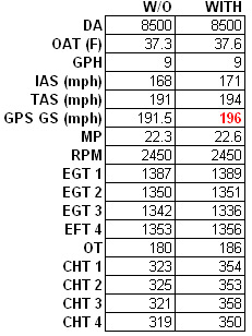
During different exhaust testing, I removed the louvers that were in the cowl and made exhaust exit ramps. This mod showed no speed loss or gain. I then decided to fabricate a sub cowl that attached to the original cowl, make it easily removable and allow some air to exit with the hope that I might see some positive things from it. I took some home type foam insulation and started shaping and sanding to make a mold. I painted 3 layers of latex house type primer to protect the foam, applied release agent, and laid up glass cloth over it. It fit up to the existing cowl very well. I actually flew it a number of times in the raw to see how it would do before spending time to finish it. The data below is a culmination of many flights rather than relying on just a few to prove what exactly this contraption was doing. My overall observation is that it is the biggest speed gain I have ever accomplished by doing one mod. The test flights were done back to back with and without the sub cowl mounted to get the performance to be as close as possible. A total of 8 flights were done this way.Flight without sub cowl mounted:
Density Altitude 8500ft. OAT 37.3F, GPH 9.0 IAS 168mph TAS 191mph GPS ground speed (flew the box and averaged speed) 191.5mph MP 22.3 RPM 2450 EGT #1 1387 #2 1350 #3 1342 #4 1353. Oil Temp 180 F. Cyl head temp #1 323 #2 325 #3 321 #4 319.
Flight with sub cowl mounted
Density Altitude 8500 ft. OAT 37.6F GPH 9.0 IAS 171mph TAS 194mph GPS ground speed (flew the box and averaged speed) 196mph MP 22.6 RPM 2450 EGT #1 1389 #2 1351 #3 1336 #4 1356 Oil temp 186 F. Cyl head temp #1 354 #2 353 #3 358 #4 350.4.5 mph increase.
Note the MP is slightly higher with the sub cowl mounted as I believe the air has changed pressure in the plenum. I have already made another unit and will install it with the original M1B crossover exhaust and modify it with stainless inserts so that system will work as well. The exhaust exit ramps will be removed and the original louvers re-installed. This next test will show if there is any performance improvement with a standard set up. Don't look for this in the next couple of weeks as all this stuff takes time. No, I am not interested in manufacturing these units, as I am sure there is a large variations in existing exit sizes with each individual aircraft, This is very easy to do so if interested, a builder should be able to make one with no problem. The shape is not set in stone, and I can see a real craftsman adding a cockpit controlled cowl flap.
Isn't this experimental world we live in a lot of fun?"
Larry Vetterman"


All photographs here courtesy Larry VettermanVetterman Sub Cowl Mod: v2.0 ...an update on Larry's quest to get more speed.